Managing the world of electronics can be daunting, but using a PCB prototype board simplifies the process. These boards allow designers and hobbyists to test their circuits before committing to a final design, saving time and resources. This article explores essential tips and techniques for effectively utilizing a PCB prototype board, empowering creators to bring their ideas to life with confidence.
Understanding PCB Prototype Boards
PCB prototype boards serve as essential tools for testing and refining circuit designs. These boards allow engineers and hobbyists to experiment with electronic components without the commitment of a printed circuit board (PCB) production run.
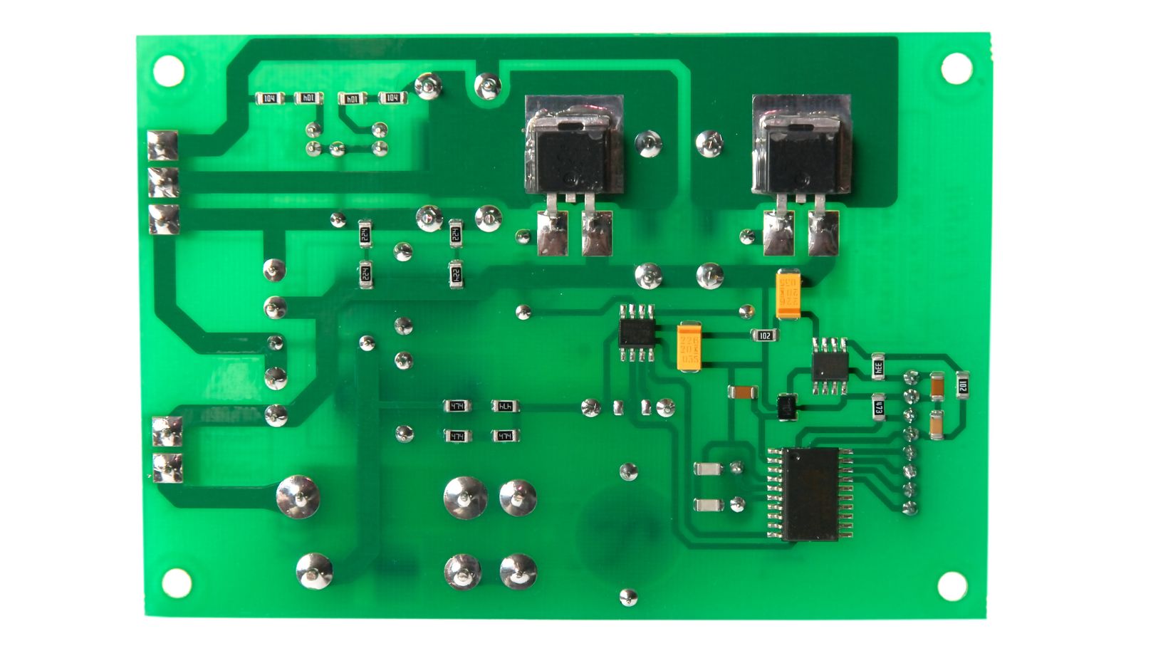
What Is a PCB Prototype Board?
A PCB prototype board, often referred to as a prototyping board, features a grid of holes and conducting tracks. Users insert electronic components into these holes to create temporary circuits. The most common types of prototype boards are solderless breadboards and perf boards. Solderless breadboards allow for easy component adjustments without permanent soldering, while perf boards require soldering for more stable connections.
Importance of PCB Prototyping
PCB prototyping plays a crucial role in the development of electronic devices. It enables users to test designs quickly and efficiently, reducing the risk of errors in the final product. By validating circuit functionality before committing to a full production run, designers save both time and resources. Prototyping facilitates troubleshooting, allowing for easy identification and rectification of issues in the design phase.
Preparing for Your Project
Preparing for a PCB prototyping project requires a thoughtful selection of components and tools. By ensuring the right setup, users improve the efficiency of their testing and experimentation.
Selecting the Right Prototype Board
Selecting the correct prototype board significantly impacts the project’s outcome. Common board types include:
Solderless Breadboards: Ideal for quick prototypes, these boards allow for easy component insertion and removal without soldering.
Perf Boards: Suitable for more permanent setups, perf boards require soldering and offer flexibility for circuit design.
Custom PCB Prototypes: For complex projects, custom boards designed specifically for the application can provide the most reliable results.
When choosing a board, consider factors like the complexity of the circuit, the necessary component connections, and personal preferences for reusability or permanence.
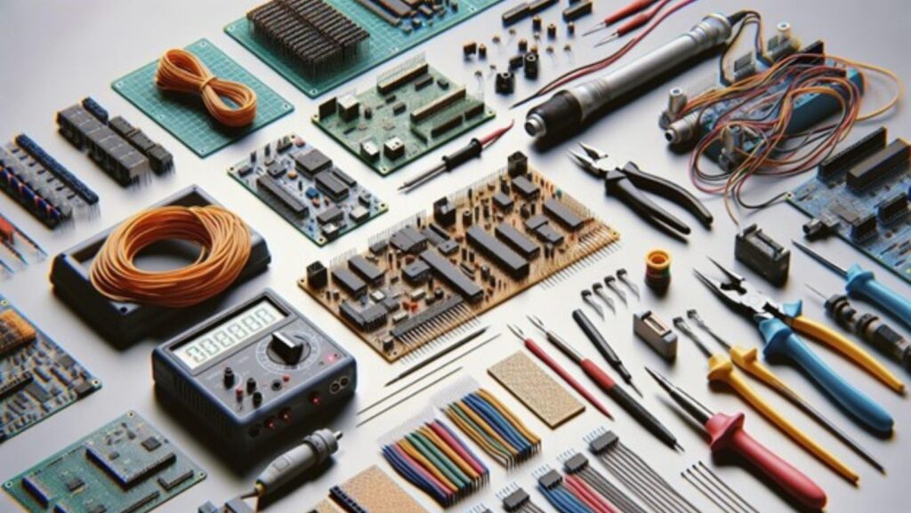
Essential Tools and Materials
Gathering essential tools and materials ensures a smooth prototyping process. Key items include:
Wire Strippers: Used for preparing wire ends to connect components.
Soldering Iron: Necessary for permanent connections on perf boards and custom PCBs.
Multimeter: Vital for measuring voltage, current, and resistance, helping troubleshoot circuits.
Jumper Wires: Allow for easy connections between components on solderless breadboards.
Power Supply: Ensure an adequate and appropriate power source for the circuit under test.
Assembling these items prior to starting helps streamline the workflow and minimizes interruptions during testing phases.
Step-by-Step Guide to Using a PCB Prototype Board
Using a PCB prototype board involves a systematic approach to design, transfer, and assembly. Follow these steps for effective prototyping.
Designing Your Circuit
Designing a circuit requires careful planning and consideration of each component’s role. First, select components like resistors, capacitors, and microcontrollers based on project specifications. Next, use circuit design software to create a schematic diagram that visualizes the connections between components. This diagram serves as a blueprint for the assembly process, ensuring accuracy in the final build. Check connections in the diagram before moving on to the next step.
Transferring the Design to the Board
Transferring the circuit design to the prototype board starts with positioning components correctly. Lay out each component on the board according to the schematic, ensuring that the component leads correspond with the designated holes or areas on the board. For solderless breadboards, insert leads into the appropriate rows and columns, maintaining organized connections. For perf boards, pre-drill holes if necessary, and ensure adequate spacing between components for effective wiring.
Soldering Components
Soldering components involves the precise application of solder to create strong electrical connections. Start by securing components in the correct positions. Heat the soldering iron and apply it to the joint where the component lead meets the board. Introduce the solder until it flows evenly around the connection, creating a stable joint. Allow the joint to cool before moving on to the next connection. Inspect each joint for quality; clean any excess solder or debris for optimal performance.
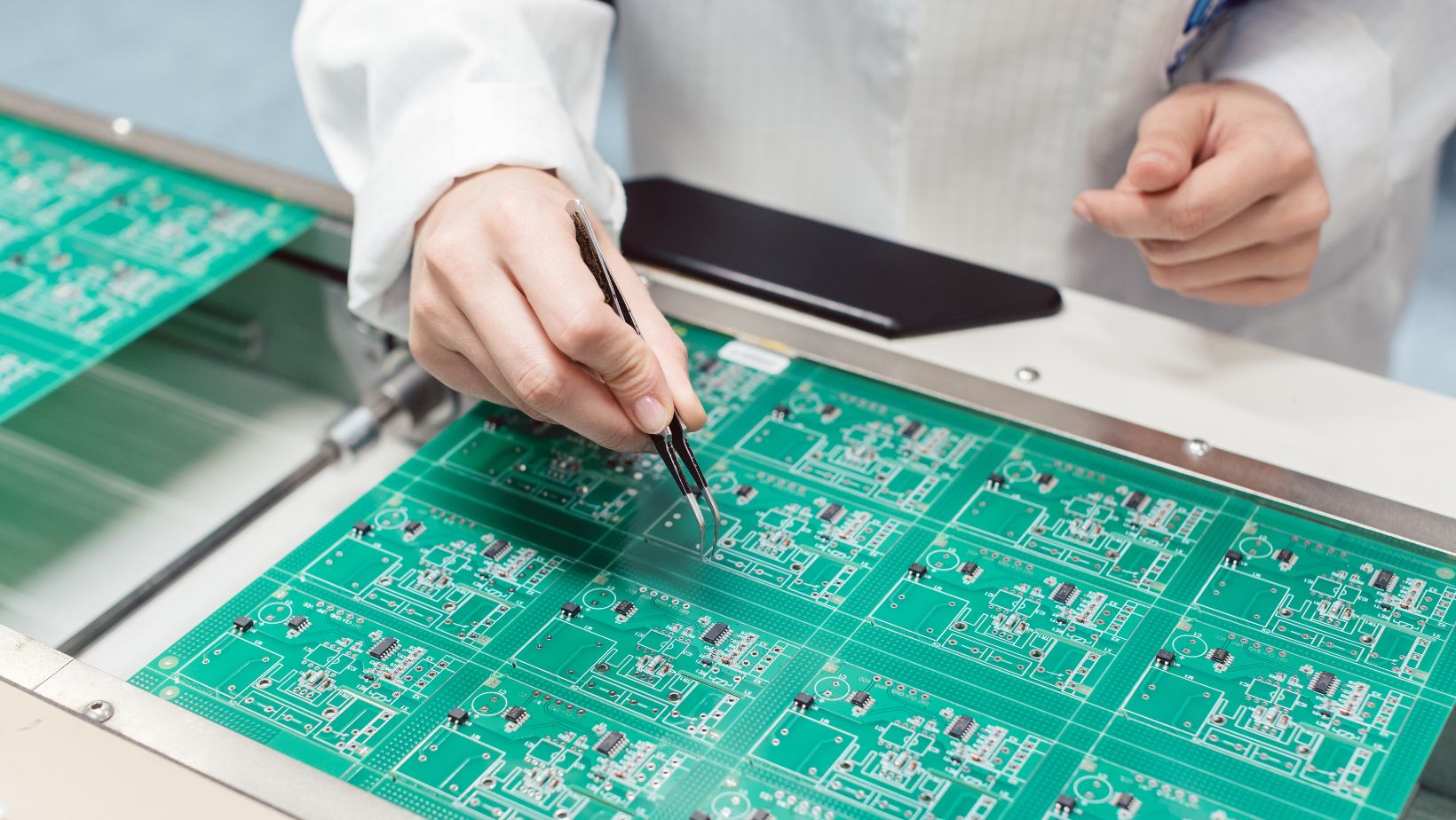
Testing Your Prototype
Testing a PCB prototype ensures the functionality and reliability of the circuit design. This process allows one to verify that the circuit operates as intended before final production.
Methods for Testing PCB Functionality
Visual Inspection: Conduct a thorough visual inspection of the prototype for soldering defects, misaligned components, or any physical damage. This initial step helps identify obvious issues quickly.
Power Supply Check: Connect the PCB to a suitable power supply. Monitor current draw to ensure it aligns with expected values. Anomalies may indicate problems within the circuit.
Multimeter Testing: Utilize a multimeter to measure voltages, resistances, and continuity across various points on the PCB. This helps confirm that signals flow correctly through components.
Signal Testing: Use an oscilloscope to observe signal integrity on critical nodes. Analyze waveforms to detect any distortion or unexpected behavior which may affect performance.
Functionality Testing: Execute specific tasks the circuit is designed for, such as data transmission or sensor activation. Confirm that the prototype meets all functional requirements.
No Power: If the board shows no power, check power supply connections and ensure the correct voltage is supplied. Inspect for any short circuits.
Incorrect Readings: If a multimeter or oscilloscope indicates incorrect values, verify component orientations and values. Replace any faulty components.
Overheating Components: Monitor temperature and ensure no components exceed their rated limits. Replace or reconfigure as necessary to prevent damage.
Unresponsive Functions: If certain functions fail to operate, review the circuit diagram and components involved. Conduct step-by-step testing to isolate and address the issue.
Intermittent Connections: For issues with intermittent operation, inspect solder joints and connector integrity. Reflow solder or replace connectors to restore reliability.
Ideal Practices for PCB Prototyping
Effective PCB prototyping enhances project outcomes. Following best practices ensures accuracy, efficiency, and reliability throughout the process.
Tips for Enhanced Performance
Select Quality Components: Use components that meet the required specifications to increase reliability and performance.
Utilize Proper Tools: Employ tools designed for PCB work, such as soldering stations, multimeters, and oscilloscopes, to ensure accurate results.
Implement Clear Layouts: Design PCBs with intuitive layouts to reduce the risk of errors during assembly and testing.
Test Iteratively: Conduct tests at each stage of PCB development to identify and resolve issues early in the process.
Document Changes: Keep detailed records of revisions made to the PCB design to maintain clarity and traceability throughout development.
Neglecting Documentation: Failing to document the design process can lead to confusion and repeated errors.
Choosing Inappropriate Components: Using components that are incompatible with the project can result in malfunctions or failures.
Skipping Power Checks: Overlooking power supply checks can lead to unresponsive boards or component damage.
Rushing the Testing Phase: Inadequate testing may miss critical issues, leading to reduced reliability in final products.
Ignoring Thermal Management: Underestimating heat dissipation needs can cause overheating and component failure.
Conclusion
Using a PCB prototype board effectively can significantly improve the design and testing process. By carefully selecting components and following a structured testing approach, individuals can identify and resolve issues early on. This not only improves the reliability of the final product but also streamlines the development timeline.
Adhering to best practices ensures that the prototyping phase is both efficient and informative. Proper documentation and iterative testing play crucial roles in refining designs. Ultimately, a well-executed PCB prototyping process lays a solid foundation for successful electronic projects, paving the way for innovation and reliability in the final outcomes.